Arduino Led Pin 13 - Arduino to LCD Panel 1 Interface / The relay is active low and i soldered pins 12 and 13 of the pro mini to in1 and in2 of the relay.
Arduino Led Pin 13 - Arduino to LCD Panel 1 Interface / The relay is active low and i soldered pins 12 and 13 of the pro mini to in1 and in2 of the relay.. Defines pin 13 as an output pin and gives it the name ledpin. I have about a dozen arduino pro boards that i've bought from sparkfun over the past 8 months, usually in orders of 3 or 4 at a time. As a way of adjusting the pulse length, the code below just repeatedly writes the pin high then repeatedly writes the pin low, based on the value of portreps. Configures the specified pin to behave either as an input or an output. Use this led to perform blinky operations.
The reference voltage for the internal adc is by default set to 5v. The delay () causes the arduino to wait for the specified number of milliseconds before continuing on to the next line. * led attached from pin 13 to ground * pushbutton attached to pin 2 from +5v * 10k resistor attached to pin 2 from ground * note: The arduino digital pins can read only two states: Used for iic communication using wire library.
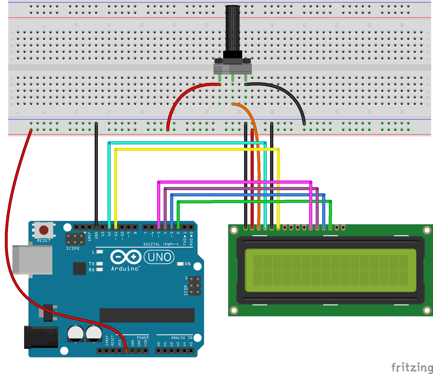
How to set up an LCD with Arduino - Programming ... from www.programmingelectronics.com Upload the rx/tx blinky, hello world sketch Errors and blinking pin 13 led on arduino pro #132994. The code makes the digital pin 13 an output and toggles it by alternating between high and low at one second pace. The led's legs are connected to two pins on the arduino: /* button turns on and off a light emitting diode(led) connected to digital pin 13, when pressing a pushbutton attached to pin 2. See the digital pins page for details on the functionality of the pins. After a call to analogwrite(), the pin will generate a steady rectangular wave of the specified duty cycle until the next call to analogwrite() (or a call to digitalread() or digitalwrite()) on the same pin. Writes an analog value to a pin.can be used to light a led at varying brightnesses or drive a motor at various speeds.
See the digital pins page for details on the functionality of the pins.
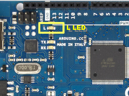
50kohm) to make this less confusing. The reference voltage for the internal adc is by default set to 5v. Also see tutorial about digital pins on the arduino website. As of arduino 1.0.1, it is possible to enable the internal pullup resistors with the mode input_pullup. Upload the rx/tx blinky, hello world sketch This little sketch will execute a port command against arduino pin 13. Über 7 millionen englischsprachige bücher. The arduino's pin 13 led should light up when the push button is pressed, and turn off when the button is released. This led is connected to the digital i/o pin #13 in most boards. All leds, regardless of size, require some form of current limiting. In some boards, like the arduino mkr series, it's linked to the pin #6. The arduino boards aren't very good for use on batteries, which is sort of strange considering what people want to use them for. You can set the port 13 by program (using it as output port) or you pull down the port by connecting it to ground (using it as input port).
The relay is active low and i soldered pins 12 and 13 of the pro mini to in1 and in2 of the relay. The only problem i am having is that the led on pin 13 wont stop flashing! Errors and blinking pin 13 led on arduino pro #132994. Digital pin 13 is harder to use as a digital input than the other digital pins because it has an led and resistor attached to it that's soldered to the board on most boards. When the forward voltage of the led is applied, it turns into a short circuit.
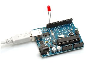
Note2 - Blink sketch | embeddist from c2.staticflickr.com Without it, you'll get a warning that the led might burn out soon. Spend some time experimenting with different pins. Commands for controlling led will be sent by smartphone via app named serial bluetooth terminal for android. Used to provide reference voltage for analog inputs with analogreference() function. Uno pin 13 led mysteriously always on at 0.14v unless pinmode output (3 answers) closed 3 years ago. This little sketch will execute a port command against arduino pin 13. On the arduino uno, it is near pin #13: I went through the tutorials and installed all the drivers and software needed, and i simply plugged it in my mac via usb and it will not stop blinking.
In any case you can reference the exact pin using.
Configures the specified pin to behave either as an input or an output. The transmitter pin and receiver pin are used to transmit and receive the data resp. I2c a4 (sda) and a5 (sca): The relay is active low and i soldered pins 12 and 13 of the pro mini to in1 and in2 of the relay. This pin is also known as a uart pin. Commands for controlling led will be sent by smartphone via app named serial bluetooth terminal for android. However, this voltage is buffered by the uno's op amp, and repeated on the output. Defines pin 2 as an input pin and gives it the name inputpin. This op amp will be able to power up an led, and apperently, it does. Making this pin low, resets the. In any case you can reference the exact pin using. This led is connected to the digital i/o pin #13 in most boards. After a call to analogwrite(), the pin will generate a steady rectangular wave of the specified duty cycle until the next call to analogwrite() (or a call to digitalread() or digitalwrite()) on the same pin.
Errors and blinking pin 13 led on arduino pro #132994. Without setting the digital port 13 the led is turned on. Set the ledpin (pin 13) to high, or 5 volts. /* button turns on and off a light emitting diode(led) connected to digital pin 13, when pressing a pushbutton attached to pin 2. In fact, the only leds on the board are the power indicator, and rx/tx blinkies.
Control Your LED In The Serial Monitor Using Arduino Uno from www.c-sharpcorner.com The led's legs are connected to two pins on the arduino: Hi, i just received my arduino starter kit and want to get started. Set the ledpin (pin 13) to high, or 5 volts. On the arduino uno, it is near pin #13: Also see tutorial about digital pins on the arduino website. When there is a voltage signal and when there is no signal. In any case you can reference the exact pin using. Defines pin 2 as an input pin and gives it the name inputpin.
When there is a voltage signal and when there is no signal.
In the past few weeks, 4 of the boards have started getting flaky. On the arduino uno, it is near pin #13: The arduino does not remember any states which have been set before a new program start. Unlike other arduino boards, though, we can control the rx/tx leds in our sketch. Uno pin 13 led mysteriously always on at 0.14v unless pinmode output (3 answers) closed 3 years ago. You can set the port 13 by program (using it as output port) or you pull down the port by connecting it to ground (using it as input port). Pin 13 is sck for spi. The pin numbers 2 to 13 are used as pwm pins. The arduino boards aren't very good for use on batteries, which is sort of strange considering what people want to use them for. It's important to note that: I2c a4 (sda) and a5 (sca): In fact, the only leds on the board are the power indicator, and rx/tx blinkies. When the forward voltage of the led is applied, it turns into a short circuit.
Belum ada Komentar untuk "Arduino Led Pin 13 - Arduino to LCD Panel 1 Interface / The relay is active low and i soldered pins 12 and 13 of the pro mini to in1 and in2 of the relay."
Belum ada Komentar untuk "Arduino Led Pin 13 - Arduino to LCD Panel 1 Interface / The relay is active low and i soldered pins 12 and 13 of the pro mini to in1 and in2 of the relay."
Posting Komentar